Integrated Reformer Combined Cycle Process Flow Diagram Flow
Combined cycle power: history, description & uses Solved consider the combined cycle system flow diagram shown Reformer four reformers parallel series
MPE MANN Refinery Naphtha Reformer Plant Commissioning and PGTR – UPCEM
Combined cycle solutions Integrated process flow diagram. Cycle combined system plant schematic schematics turbine heat generator exhaust
-four types of reformer arrangement: single primary reformer (a
Reforming section flowsheet with a pre-reformerReforming cycle Flowchart of the primary reformer.Definition of combined power cycle,co-generation system and effectiveness.
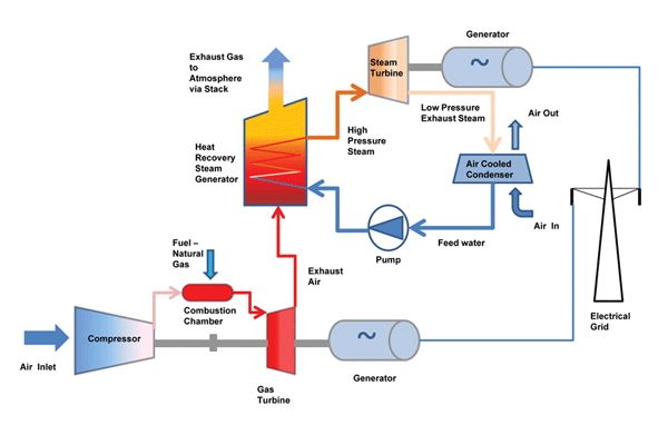
Cycle effectivenessCycle process turbine cogeneration extracted recovered Schematic flow diagram of combined cycle power plant.What are combined cycle power plant principles -theory-design and.
Mpe mann refinery naphtha reformer plant commissioning and pgtr – upcem
Process flow diagram of combined cycle for case 2.Schematic flow diagram of combined cycle power plant. Process flow diagrams of the studied combined cycle systems. (aReformer arrangement.
Cycle combined plant power operationHrsg triple Cycle combined power plant mogas diagram turbine steam flow gas process valve generation engine typical powergen sub twoThe traditional integrated solar combined cycle system with changeable.

5. process diagram depicting the combined cycle reference plant
Process flow sheet of integrated reforming combined cycleSolved consider the combined cycle system flow diagram shown Fig: combined cycle process flow diagramSchematic representation of combined cycle with: a) single pressure.
Reformer flowchartSystem schematics Process flow diagram of the integrated system.Flow steam integrated retrofit configuration generator extraction providing.

Ccgt cycle plant combined power turbine diagram steam schematic principle working simple engineering
Flowsheet of the integrated process.Working principle of combined cycle power plant Secondary reforming flowsheets-four types of reformer arrangement: single primary reformer (a.
Combined cycle power plant diagramIntegrated process flow diagram Process flow diagram of the standard integrated retrofit configurationProcess flow diagram with control loops for the integrated system.

The figure below shows a combined cycle formed by
Sales process integration flowchartComplete integrated system flow chart. Schematic process flow diagram of the proposed integrated-systemCombined cycle systems.
Cycle combined gas turbine rankine topping organic bottoming formed shows figure below air chegg steady cycles answer .


Integrated Process Flow Diagram | Download Scientific Diagram

What are Combined Cycle Power Plant Principles -Theory-Design and

The traditional integrated solar combined cycle system with changeable

Combined Cycle Power Plant Diagram

Secondary Reforming Flowsheets

MPE MANN Refinery Naphtha Reformer Plant Commissioning and PGTR – UPCEM

Complete integrated system flow chart. | Download Scientific Diagram